Measurements at frequencies beyond the analyzer's operating range (mm-wave measurements) are achieved by combining a frequency-converting measurement with an external test set (frequency converter). Rohde & Schwarz offers frequency converter types for various frequency ranges. E.g. the frequency converters R&S ZVA-Z110 and R&S ZV-Z110E extend the frequency range of R&S ZVA or R&S ZVT network analyzers to a range between 75 GHz and 110 GHz.
The test ports of the frequency converters and the connecting elements are rectangular waveguides. For the R&S ZVA-Z110(E) converter, the dimensions of the waveguides are according to EIA WR-10, equivalent to RCSR WG-27. Refer to the Quick Start Guide and the "Specifications" supplied with your converter for detailed information about the frequency range and the waveguide type of your converter model.
Two different converter types are available:
Converters without electronic attenuators. The analyzer cannot control the output power of these converters.
Converters with electronic attenuators (and a capital "E" in the type designation, e.g. R&S ZV-Z110). The output power of these converters is controlled by the analyzer; a power calibration and power sweep is possible.
 Required
equipment and options
Required
equipment and options
Frequency extension is available on ZVA and ZVT analyzers which are specified for frequencies up to 20 GHz or above (e.g. ZVT 20, ZVA24, ZVA 40). The required firmware version depends on the converter mode. Refer to the release notes (What's new) or to the Quick Start Guide of your converter.
The following additional options and accessories are needed:
One or more frequency converters, depending on the test setup.
Option R&S ZVA-K8, Converter Control. Option R&S ZVA-K8 also comprises option ZVA-K4, Arbitrary Generator and Receiver Frequencies.
Option R&S ZVA<n>-B16, Direct Generator/Receiver Access (where <n> denotes the number of test ports of the analyzer)
For converters with electronic attenuator (e.g. R&S ZVA-Z110E): Option R&S ZVA-B8 to establish the control connection between the NWA and the converter
A two-port transmission measurement requires two frequency converters plus a four-port network analyzer or a two-port analyzer with an external generator (see External Generators). The external generator must provide frequencies up to 20 GHz or above and sufficient signal power. Reflection measurements can be performed with a two-port analyzer without external generator.
The external generator must be synchronized to the network analyzer using the 10 MHz reference clock signal. It is not possible to use several external generators simultaneously.
A suitable set of calibration standards
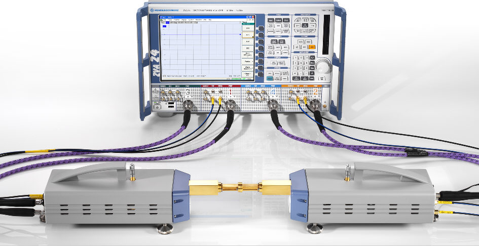
The frequency converters use frequency multipliers to transform the RF source signal from one of the network analyzer ports into a high-frequency stimulus signal. A dual directional coupler separates the reference and measurement channels from the waveguide test port. A second signal (Local Oscillator, LO) is used for down-conversion of the reference and measurement channels. The LO signal can be provided either by a second analyzer port or by an external generator. The down-converted signals are fed to the REF IN and MEAS IN input connectors of the analyzer port providing the RF source signal.
The schematic test setup for a two-port transmission measurement using four analyzer ports (no external generator) is shown below.
A measurement using converters without electronic attenuator involves the following stages:
Selection of the converter type and of the test setup in the Frequency Converter dialog
Connection of the frequency converters
System Error Correction using a suitable waveguide calibration kit
Connection of the DUT and measurement
For converters with electronic attenuators, the following additional stages are required:
Entry of power coefficients (when the converter is used for the first time)
Power and frequency settings
Power calibration
The Frequency Converter tab belongs to the System Configuration menu (System – System Config). It selects the frequency converter type and the external test setup as well as the power transfer model (especially for converters with electronic attenuators).
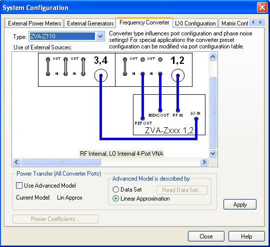
The dialog provides the following control elements:
Type selects a frequency converter type.
Use of External Sources provides the possible test setups for each converter type. The test setups differ in the way how the LO signal is provided (from the analyzer port or from an external generator).
The Power Transfer settings define the model by which the analyzer controls the output power at all converter ports. The exact meaning of the power transfer modes depends on the converter model; see Power Transfer Modes.
Apply activates the selected test setup and adjusts the analyzer settings; see information below.
For frequency converters with electronic attenuators, pressing Apply enables the Power Coefficients button. This button opens an additional dialog to enter the power coefficients for the electronic attenuators.
The frequency-converter settings belong to the global resources; they are not changed upon a Preset or *RST.
Analyzer
settings with active frequency converter
After a particular converter type and test setup is applied, the analyzer is automatically configured as follows:
A preset is applied.
The default frequency range of the selected converter type is set (e.g. 75 GHz to 110 GHz for R&S ZVA-Z110 converters). If no converter is selected, (Type = <NONE>), the default frequency of the network analyzer is set. The Sourcesection of the Port Configuration table shows the true output frequencies at all analyzer ports and the frequency conversion formulas.
The output powers at the RF and LO ports are set to optimum values. For converters without electronic attenuator, the output power of the converters can be reduced using the knurled adjusting knob on top of the converter.
The LO signals are permanently on; the RF source signal is present only during the partial measurements that require the respective test port as a drive port.
Low Phase Noise is enabled.
ALC (All Chans) is disabled.
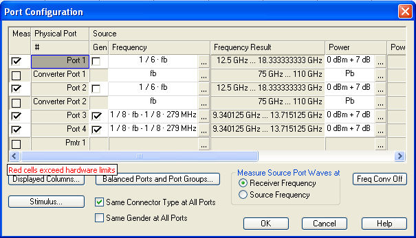
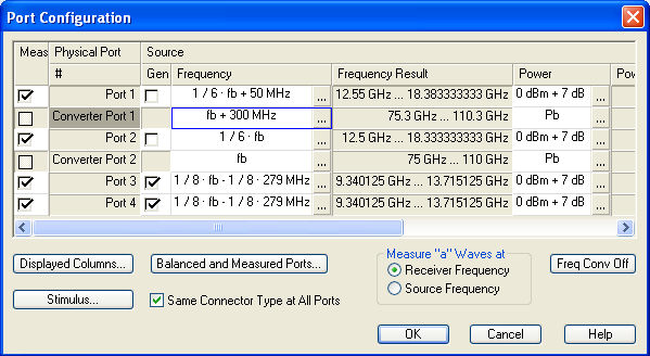
All signal settings appear in the Port Configuration dialog as soon as the frequency converter mode is active. In the example below, a sweep range between 75 GHz and 110 GHz is selected. The frequency multipliers for the RF signals have a multiplication factor of 6, so the actual output frequency at the RF ports 1 and 2 is between 12.5 GHz and 18.3333333 GHz. The frequency of the LO signal is such that the reference and measurement channels are received at the fixed IF frequency of 279 MHz (shown in the Receiver section of the Port Configuration dialog). The LO frequency is always below the RF frequency (upper sideband).
 It is also possible to define port-specific frequencies
and powers at the converter ports; see Power
and Frequency Settings.
It is also possible to define port-specific frequencies
and powers at the converter ports; see Power
and Frequency Settings.
|
Remote control: |
[SENSe<Ch>:]FREQuency:CONVersion:DEVice:MODE |
The Power Transfer (All Converter Ports) settings in the Frequency Converter tab define how the analyzer controls the output power at all converter ports. The general settings can be changed for individual converter ports (Channel – Mode – Port Configuration – Source Power – Converter Port <n> Power – Power Transfer).
 Changing the power transfer settings in the
Frequency Converter tab will
overwrite the individual port settings.
Changing the power transfer settings in the
Frequency Converter tab will
overwrite the individual port settings.
![]()
The basic power transfer model (Use Advanced Model off) is simple to configure and suitable for most standard applications.
Converters with electronic attenuators: The converter output power is controlled by the analyzer, using the power control cable and the electronic waveguide attenuators in the converters. The power coefficients of each converter must be correctly entered in the Power Coefficients dialog. A power calibration is possible. In addition, port-specific power settings allow you to account for devices with known attenuation/amplification in the test setup.
Converters without electronic attenuators: The converter output power can be varied by means of the power adjustment screw which is available for most converter models. No power calibration is possible, however, port-specific power settings allow you to account for devices with known attenuation/amplification in the test setup.
The advanced model may be based on a Data Set or on a Linear Approximation of the relation between the converter input power and the converter output power.
Data
Set is suitable for converters with electronic attenuators. The
analyzer uses a set of power calibration data to ensure accurate powers
at the reference plane. The calibration data set is acquired by the R&S ZVA Frequency Converter Leveling Tool,
a software utility which is available for download on the R&S ZVA
product pages (http://www.rohde-schwarz.com/product/zva).
For detailed information about the calibration procedure refer to the
leveling tool's help system.
The leveling tool can automatically acquire calibration data over a
wide range of powers and frequencies. This power transfer model is recommended
for best accuracy, in particular if large sets of calibration data are
required. If Data Set is active,
the Read Data Set button allows
you to select the calibration data folder (Calibration
Subdirectory) for the current channel, in accordance with
the definitions in the leveling tool.
Linear
Approximation is suitable for all converter types. Converters with
electronic attenuators are controlled by a combination of the RF input
power (i.e. the source power at the analyzer test port providing the signal
fed to RF IN) and the electronic waveguide attenuators in the converters.
At sufficiently high converter output powers, the electronic waveguide
attenuator settings are fixed. In the low converter output power range,
a selectable portion of the attenuation is achieved by the waveguide attenuators.
This advanced power transfer model provides a maximum dynamic range while
maintaining the spectral purity of the converter output signal in the
low-power range.
Converters without electronic attenuators are controlled by the power
adjustment screw. It is possible to adjust the screw to a desired attenuation
value and use this value as a correction factor for the port power.
The settings for the linear approximation appear in the Power
Transfer dialog.
The following table shows an overview of the different modes.
|
Power Transfer Model |
Converters with electronic attenuators |
Converters without electronic attenuators |
|
Basic |
Electronic waveguide attenuators in the converters |
(Power adjustment screw) |
|
Advanced, data set |
Measured set of attenuation values (power calibration data) |
Not supported |
|
Advanced, linear approximation |
Combination of RF input power (network analyzer) and electronic waveguide attenuators (converter) |
Mechanical attenuator setting (Power Transfer dialog) and power adjustment screw |
|
Remote control: |
[SENSe<Ch>:]CONVerter:AMODel
|
The Power Coefficients dialog is used to enter the power coefficients of converters with external attenuators. It can be opened from the System Configuration – Frequency Converter tab after the converter is activated.
For accurate control of the converter output power, the R&S ZVA analyzer must know the (non-linear) current-power characteristic of the converters. The characteristic is sufficiently described by a third-order polynomial. A label with the four polynomial coefficients c0, c1, c2, and c3 is affixed to each converter.
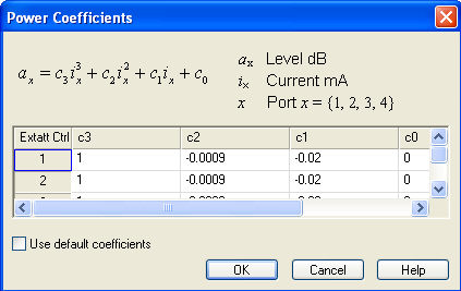
The number of rows in the table is equal to the number of analyzer ports. Each row contains the power coefficients for the converter connected to the NWA port in the fist, non-editable column. Overwrite the coefficients in a row whenever you connect a new converter to the corresponding NWA port.
Use default coefficients overwrites the entire table with a set of default power coefficients, providing acceptable output power control for arbitrary converters. For accurate measurements, use the actual power coefficients of each converter.
|
Remote control: |
[SENSe<Ch>:]FREQuency:CONVersion:DEVice:PCOefficient<Port>
|
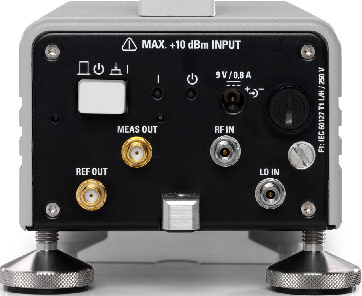
Each frequency converter must be connected to the DUT, the network analyzer, and the power supply. The DUT is screwed on the waveguide flange at the front of the converter. The remaining connectors are located on the rear panel of the converter:
|
Attention!
|
Input powers RF IN and LO IN The RF input power at the connectors RF IN and LO IN must not exceed the maximum values quoted in the data sheet. The maximum values are below the maximum RF source power of the network analyzer. The frequency converter mode ensures compatible source powers. Before you connect your converter to the network analyzer, always activate the frequency converter mode using the Frequency Converter dialog and select the proper converter type and connecting diagram. |
Connection to the network analyzer comprises the following RF input and output signals:
RF source signal (input): Connect port 1 or port 2 of the analyzer to RF IN of the converters.
LO signal (input): Connect port 3 or port 4 of the analyzer to LO IN of the converters. Alternative: Connect an external generator signal to LO IN; see Frequency Converter dialog.
Reference signal (output): Connect REF OUT of the converters to the REF IN connector of the analyzer port providing the RF source signal. The reference signal corresponds to the incident wave (a-wave) applied to the input of the DUT.
Measurement signal (output): Connect MEAS OUT of the converters to the MEAS IN connector of the analyzer port providing the RF source signal. The measured signal corresponds to the b-wave caused due to reflection or transmission at the DUT.
For converters with electronic attenuators, an additional USB control connection between the output connector of option R& ZVA-B8 (EXTATT CTRL) on the front panel of the analyzer and the 3-pin control connector at the rear panel of the converter is required. Observe the port assignment of the NWA output connector.
The input signal at the frequency converters
must be relatively stable over the entire sweep range. Use high-quality
cables for the connection of the RF and LO input signals. Appropriate
cables for the REF OUT and MEAS OUT signals are supplied with the frequency
converters.
In view of the port arrangement at the front
panel of the analyzer, it is advantageous to use test ports 1 and 2 as
RF sources, ports 3 and 4 as LO sources. The frequencies of the RF and
LO signal must be independent, therefore do not combine a pair of ports
as RF and LO sources that is supplied by a common generator (ports 1 and
2, 3 and 4; see Coupled
test ports).
To supply the frequency converter, connect the external DC power supply provided with the converter to the 9 V / 0.5 A DC input. The power supply supports input AC voltages between 100 V and 240 V and frequencies between 47 Hz and 63 Hz. A complete test setup for a 2-port transmission measurement using converters without electronic attenuators is shown below.
Frequency
converters and true differential mode
To generate a true differential signal with two frequency converters, a
modified test setup with three independent sources is required. See background
information inBalanced Ports and Port Groups – True
Diff Mode.
|
Attention!
|
Supply voltage and power The input voltage and current must not exceed the maximum values according to the rear panel labeling or the data sheet. Always use the DC power supply included in delivery to power your frequency converter. |
While the frequency converter mode is active, the Channel – Stimulus settings of the network analyzer control the frequency and power range of the converters. In addition the Channel – Mode – Port Configuration dialog shows an additional row for each converter. The Frequency and Power settings in the Source section of the dialog serve different purposes:
The output power for each converter can be selected in the Power column. For frequency converters with electronic attenuators, a source power calibration of the converter port ensures that the analyzer will generate the selected source power.
The source frequency at the converter ports is essentially determined by the port frequency of the analyzer. The converter frequency settings in the Port Configuration dialog define the frequency axes for the source power calibrations, however, they do not actually affect the converter output frequencies. For best accuracy, ensure that the correct converter frequencies are set, especially if the test setup contains additional frequency-converting components.
Example: In the example below, the frequency at the NWA Port 1 has been increased by a 50 MHz offset. The converter source frequency six times the NWA source frequency, therefore a 300 MHz offset has been entered for Converter Port 1. This ensures a correct frequency axis during the power calibration.
|
Remote control: |
SOURce<Ch>:FREQuency<Pt>:CONVersion:ARBitrary:CFRequency
|
The output power of the frequency converter can be set manually (at the converter) only, therefore the standard source power calibration eliminating frequency response errors in the signal path between the source and the reference plane (external power meter) is not possible. A power calibration of the reference receiver (a-wave) using an external power meter, however, is possible and recommended for measurements concerning the wave quantities a and b. Proceed as follows:
Ensure that the output power of the frequency converter is not attenuated (adjust the knurled knob at the top of the converter to 2 mm).
Connect an appropriate external waveguide power meter to the waveguide flange and open the Channel – Calibration – Start Power Cal – Source Power Cal dialog (see Source Power Cal).
Click Modify Settings and disable Flatness Cal, leaving Reference Receiver Cal checked.
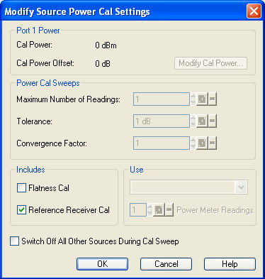
Start the calibration sweep.
This power calibration procedure ensures a reasonable accuracy of the reference power readings over a wide range of converter output powers (i.e. even if the adjusting knob is used to reduce the powers).
 A Receiver
Power Calibration
of the b-waves (without external power meter) is possible after completed
power calibration of the a-wave. Moreover, you can use the advanced power
transfer model
with linear approximation to adjust the screw to a desired attenuation
value and use this value as a correction factor for the port power.
A Receiver
Power Calibration
of the b-waves (without external power meter) is possible after completed
power calibration of the a-wave. Moreover, you can use the advanced power
transfer model
with linear approximation to adjust the screw to a desired attenuation
value and use this value as a correction factor for the port power.
After the power calibration procedure a system error correction is recommended. Due to the physical properties of the mm-waves and the waveguides, measurements with frequency converters require a special calibration kit for system error correction. Rohde & Schwarz offers special waveguide calibration kits for this purpose, e.g. the calibration kits R&S ZV-WR03, R&S ZV-WR10, and R&S WR-15. The standards in the calibration kits allow all one-port and two-port calibration types supported by the network analyzer except TNA. Refer to the documentation of the calibration kit for details.
|
Remote control: |
A source power calibration for a frequency converter requires an appropriate external power meter, to be connected to the converter's waveguide flange. Waveguide power meters are configured in the ordinary way using the System Configuration – External Power Meters tab.
To perform the source power calibration, proceed as follows:
Connect the waveguide power meter and open the Channel – Calibration – Start Power Cal – Source Power Cal dialog.
Select your converter and source port from the Source pull-down list (e.g. Conv 1 for a frequency converter connected to NWA port 1).
Click Modify Settings and ensure that both Flatness Cal and Reference Receiver Cal are checked.
If your test setup causes strong nonlinear effects, you can choose a Convergence Factor different from one.
Start the calibration sweep.
To ensure an accurate source power calibration and quick convergence, use the correct power coefficients. A receiver power calibration of the b-waves (without external power meter, using the “Receiver Power Calibration” dialog) is possible after completed source power calibration.
After the power calibration procedure a system error correction is recommended. Due to the physical properties of the mm-waves and the waveguides, measurements with frequency converters require a special calibration kit for system error correction. Rohde & Schwarz offers special waveguide calibration kits for this purpose, e.g. the calibration kits R&S ZV-WR03, R&S ZV-WR10, R&S ZV-WR12, and R&S WR15. The standards in the calibration kits allow all one-port and two-port calibration types supported by the network analyzer except TNA. Refer to the documentation of the calibration kit for details.
|
Remote control: |
SOURce<Ch>:POWer<Pt>:CORRection[:ACQuire]
|
After power calibration and system error correction, the mm-wave measurement can be performed like any other network analyzer measurement. The Port Configuration settings (together with the Stimulus settings) determine the sweep range of the converted signals (i.e the input and output frequencies at the DUT ports). All measured quantities (S-parameters, wave quantities, ratios etc.) and other trace settings are available.
The following restrictions hold for measurements with external frequency converters without external attenuators:
The measurement is performed at fixed RF source and LO power. No power sweep is possible.
To reduce the actual output power of the converters (e.g. for measuring wave quantities or testing compression effects), turn the adjusting knob on top of the converters clockwise. You will see an effect on the output power within the last 2 mm of the adjustable range.
Note the special analyzer settings listed in section Frequency Converter.
The following example shows the transmission and reflection coefficients of a bandpass filter in the frequency range between 75 GHz and 110 GHz, i.e. the measurement range of the converter R&S ZVA-Z110.