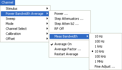
The Power Bandwidth Average menu defines the power of the internal signal source, sets the step attenuators and the IF bandwidths, and configures the sweep average.
|
|
|
Power defines the power of the internal signal source.
Step Attenuators sets the attenuation for all received and generated waves.
Step Atten. b2...sets the attenuation for the received wave b2.
RF Off switches the internal and external power sources off (if checked) or on.
Meas. Bandwidth selects the bandwidth of the IF measurement filter.
Average On activates or de-activates the sweep average. With average on the measurement results are averaged over a selected number of consecutive sweeps (Average Factor).
Average Factor defines the number of consecutive sweeps to be averaged.
Restart Average starts a new average cycle, clearing all previous results and thus eliminating their effect on the new cycle. The new cycle is started as fast as possible; an ongoing sweep is terminated immediately.
|
Remote control |
DIAGnostic:SERVice:RFPower |
Opens the numeric entry bar to set the power of the internal signal source (channel power).

The channel power determines the output power at the test ports if a Frequency Sweep, Time Sweep or CW Mode Sweep is active; see info below. The setting has no effect in Power Sweep mode, where the source power is varied over a continuous range.
 The selected channel power applies to all source ports
used in the active channel. Use the Port
Configuration
dialog to modify the output power ranges for the individual analyzer ports.
 Output power at the test ports
Power sets the output power at the test port that supplies the stimulus for the active channel. The channel power can be varied over a wide dynamic range; the range can be further increased by means of generator step attenuators. This leaves enough flexibility to include an attenuation or gain in the test setup.
The channel power can be modified by the following settings:
Generator step attenuators decrease the output power by a definite factor astep. astep can be set individually for all test ports but should not change during a sweep. To ensure a sufficient dynamic range at the test ports, it is recommended to use automatic generator step attenuator setting.
The Source section of the Port Configuration dialog provides a port-specific constant power offset (for arbitrary sweeps) and a port and frequency-dependent power slope factor (for frequency sweeps).
A generator (source) power calibration generally modifies the channel power so that Power is equal to the power at the calibrated reference plane.
The Port <port_no> Source Powerdialog gives an overview of all power settings.
|
Remote control: |
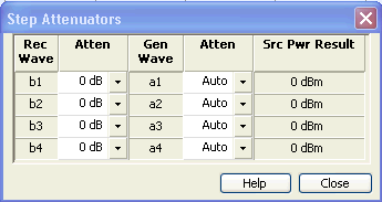
Opens a dialog to set the attenuation for the received and generated waves. The generator attenuation can be set automatically; see Automatic generator attenuation. Step attenuators can also improve the measurement accuracy for special test scenarios; see "Low Noise" generator attenuation mode.

The Step Attenuators dialog contains the following columns:
Rec. Wave lists the received waves b1 to bn. n is equal to the total number of test ports of the analyzer.
Attenuation is used to enter the attenuation for each wave bn.
Gen. Wave lists the generated waves a1 to an.
Attenuation is used to enter the attenuation for each wave an. If Auto is selected, the analyzer automatically optimizes the generator attenuation according to the current channels settings. "Low Noise" setting minimizes the broadband noise, especially at low signal levels and for analyzers with a large frequency range; see background information below.
Src Pwr Result displays the source power according to the current channel and generator attenuator settings.
Attenuation factors can be entered only for ports where a receiver or generator step attenuator is installed.
 Generator
and receiver step attenuators
Receiver and generator step attenuators can be purchased as ZVA options. The following attenuators are available:
|
|
Port 1 |
Port 2 |
Port 3 |
Port 4 |
|
ZVA8, generator |
ZVA8-B21 |
ZVA8-B22 |
ZVA8-B23 |
ZVA8-B24 |
|
ZVA8, receiver |
ZVA8-B31 |
ZVA8-B32 |
ZVA8-B33 |
ZVA8-B34 |
|
ZVA24, generator |
ZVA24-B21 |
ZVA24-B22 |
ZVA24-B23 |
ZVA24-B24 |
|
ZVA24, receiver |
ZVA24-B31 |
ZVA24-B32 |
ZVA24-B33 |
ZVA24-B34 |
|
ZVA40, generator |
ZVA40-B21 |
ZVA40-B22 |
ZVA40-B23 |
ZVA40-B24 |
|
ZVA40, receiver |
ZVA40-B31 |
ZVA40-B32 |
ZVA40-B33 |
ZVA40-B34 |
|
ZVA50, generator |
ZVA50-B21 |
ZVA50-B22 |
ZVA50-B23 |
ZVA50-B24 |
|
ZVA50, receiver |
ZVA50-B31 |
ZVA50-B32 |
ZVA50-B33 |
ZVA50-B34 |
|
ZVA67, generator |
ZVA67-B21 |
ZVA67-B22 |
ZVA67-B23 |
ZVA67-B24 |
|
ZVA67, receiver |
ZVA67-B31 |
ZVA67-B32 |
ZVA67-B33 |
ZVA67-B34 |
Refer to the data sheet for detailed ordering information and technical specifications.
Attenuation factors for the received waves and the generated waves serve different purposes:
 Automatic generator attenuation
The aim of the automatic attenuator setting is to ensure that the analyzer can perform the entire sweep without switching the generator step attenuators. The output power pel at each port depends on the following settings:
The channel power pch (the Powerset in the Channel –Power Bandwidth Average menu).
The port-specific power offset pb (for arbitrary sweeps) and the port and frequency-dependent power slope factor pSlope (for frequency sweeps) defined in the Receiver section of the Port Configuration dialog.
A port and stimulus-dependent correction factor pcorr introduced by a generator (source) power calibration.
The port-specific generator step attenuator setting astep.
If everything is expressed in dB units, the output power pel at each port must be equal to the sum of the channel power and all port and stimulus-dependent correction factors:
pel = pch + pb + pSlope + pcorr + astep
The automatic attenuator setting algorithm selects astep such that the variation range for pel is sufficient to account for the stimulus-dependent variations of pb and pSlope, and pcorr. If this is not possible in a particular subrange of the sweep (e.g. because the sweep settings are such that an excess variation range for pel or a negative attenuation factor astep would be required) then the analyzer generates an error message.
 "Low
Noise" generator attenuation mode
In "Low Noise" mode, the automatic attenuator setting algorithm is modified in order to minimize the broadband noise in the generator signal. The modification can narrow the dynamic range that the generator covers without switching the attenuator. Use this mode if the following criteria apply:
Your test setup contains a broadband power meter (that you use e.g. for a power calibration).
Your generator levels are not significantly above the broadband noise level; see table below.
Your analyzer supports a large frequency range (this applies to the high-frequency models, see table below).
The amount of broadband noise in the generator signal increases with the total bandwidth of the network analyzer. The following table gives an overview for the different R&S ZVA analyzer models.
|
R&S ZVA analyzer model |
Typical broadband noise |
|
R&S ZVA 8 |
–32 dBm |
|
R&S ZVA 24 |
–25 dBm |
|
R&S ZVA 40 |
–21 dBm (< 24 GHz) and –25 dBm (> 24 GHz) |
|
RZS ZVA 50 |
–20 dBm (< 24 GHz) and –13 dBm (> 24 GHz) |
 A new system error correction
is recommended whenever the step attenuator settings are changed. A change
of the generator step attenuator settings may also occur in Auto
mode; see above.
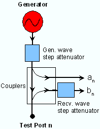
The position and function of the step attenuators is illustrated in the following figure. The analyzer measures both the attenuated generated waves and the attenuated waves received from the DUT.

Opens the numeric entry bar to set the attenuation for the received wave b2. This function is available only if a receiver step attenuator is installed at port 2.

The attenuation is used to adjust the received signal level at port 2 to the input level range of the analyzer in order to avoid damage to the instrument, e.g. if the DUT is a power amplifier. The range of values depends on the analyzer model.
Using a single step attenuation b2 corresponds to a standard test setup with 0 dB generator attenuation and attenuation of the (amplified) wave received at test port 2. The attenuation factors for all received and generated waves can be set via Step Attenuators.
|
Remote control: |
INPut<Pt>:ATTenuation |
RF Off switches the internal and external power sources off (if checked) or on. Switching off the RF power helps to prevent overheating of a connected DUT while no measurement results are taken. The exact behavior of RF Off is part of the system configuration; refer to the description of the Power tab.
 After the RF power is switched on, the start
of the measurement is delayed by approx. 1 s while the amplifier stages
of the analyzer are allowed to settle. To avoid this delay, reduce the
base channel power setting or turn off the drive ports in the Port
Configuration
dialog instead of using RF Off.
 Switching off the internal
RF generator while an external generator is used can improve the measurement
accuracy. RF Off also deactivates
external generators, so you have to use the settings in the Source
section of the Port Configuration
dialog (with option R&S ZVA-K4).
|
Remote control: |
Sets the measurement bandwidth of the IF filter. Meas Bandwidth opens a submenu to select bandwidths between 10 Hz and 1 MHz:

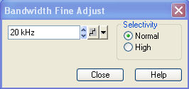
Fine Adjust... opens a dialog where you can modify the selected measurement bandwidth and the selectivity of the IF filter.

The numeric entry field shows the last IF filter bandwidth selected. The arrow buttons increment and decrement the bandwidth in 1-2-5 steps for each decade. Entered values between the steps will be rounded up, values exceeding the maximum bandwidth rounded down.
Selectivity selects between two types of IF filters: Filters with Normal selectivity and short settling time, and filters with High selectivity but larger settling time.
The selected bandwidth and selectivity applies to all filters used in the current channel. This makes sense because the measurement speed is limited by the slowest filter in the channel. In Segmented Frequency sweeps, the bandwidth and selectivity can be set independently for each segment; see Define Segments.
 Optimizing the filter settings
A high selectivity and a small filter bandwidth both suppress the noise level around the measurement frequency and thus increase the dynamic range. On the other hand the time needed to acquire a single measurement point increases for small filter bandwidths and high selectivity. For small bandwidths, the filter settling time, which is inversely proportional to the bandwidth, is responsible for the predominant part of the measurement time.
The characteristics of the high selectivity filter makes it particularly suitable for isolating unexpected spurious responses or known mixer products.
 In general, the
system error correction is no longer valid after a change of the IF filter
bandwidth. The message Cal? appears
in the trace list.
 Optimizing
the measurement speed
|
Remote control: |
[SENSe<Ch>:]BANDwidth|BWIDth[:RESolution] |
Opens the numeric entry bar to define the number of consecutive sweeps to be averaged.

An average over several sweeps reduces the influence of random effects in the measurement and therefore minimizes the noise level. The effect increases with the average factor, however, obtaining an averaged result requires several sweeps and therefore increases the measurement time.
 In contrast to the sweep
count
(for single sweep mode), averaging is always channel-specific. Both features
are completely independent from each other.
The average factor is also valid for calibration sweeps: The calculation
of system correction data is based on the averaged trace.
 Smoothing
is an alternative method of compensating for random effects on the trace
by averaging adjacent measurement points. Compared to the sweep average,
smoothing does not significantly increase the measurement time but can
eliminate narrow peaks and thus produce misleading results.
The sweep average is not frequency selective. To eliminate a spurious signal in the vicinity of the measurement frequency, alternative techniques (e.g. a smaller filter bandwidth) must be used.
The average trace is obtained as follows:
Let c be the Average Factor and assume that n sweeps have been measured since the start of the average cycle (start of the measurement or Restart Average). The following two situations are distinguished:
n < c: At each sweep point, the average trace no. n is calculated from the average trace no. n 1 and the current trace no. n according to the following recurrence:

The average trace represents the arithmetic mean value over all n sweeps.
n > c: At each sweep point, the average trace no. n is calculated from the average trace no. n 1 and the current trace no. n according to:

The formulas hold for Average Factor n = 1 where the average trace becomes equal to the current trace.
 Optimizing
the measurement speed
|
Remote control: |
[SENSe<Ch>:]AVERage[:STATe]
ON | OFF |