The Channel Select submenu provides functions to create and delete channels and select a channel as the active channel.
|
|
|
Next Channel selects the next channel as the active channel (disabled if only one channel is defined).
Select Channel opens a box to select an arbitrary channel of the active setup as the active channel (disabled if only one channel is defined).
Add Channel + Trace creates a new channel and a new trace in the active diagram area.
Add Channel + Trace + Diag Area creates a new channel and a new trace in a new diagram area.
Delete Channel deletes the active channel.
Channel Manager opens a dialog to perform the previous actions systematically, rename channels.
 Active
and inactive traces and channels
Active
and inactive traces and channels
A window can display several diagram areas simultaneously, each with a variable number of traces. One of these traces is active at each time. The active trace is highlighted in the trace list on top of the active diagram area (Trc 4 in the figure below):
A mouse click onto a trace in the list selects the trace as the active trace. Alternatively, use the functions of the Trace –Tracesmenu.
The active channel is the channel which belongs to the active trace. The channels of all traces in a diagram area are listed at the bottom of the diagram, together with the Stimulus values and the display colors of all traces. The active channel is highlighted (Ch1 in the example below, with two associated traces).
A mouse click onto a trace in the trace list selects the channel associated to the trace as the active channel. Channels with no traces are not indicated in the diagram areas but can be accessed via the Channel Manager.
 You can monitor the channel activity using the OUTPut<Ch>:UPORt[:VALue]
<numeric_value>
command and the output signals at pins 8 to 11 of the USER CONTROL connector.
You can monitor the channel activity using the OUTPut<Ch>:UPORt[:VALue]
<numeric_value>
command and the output signals at pins 8 to 11 of the USER CONTROL connector.
Selects the next channel in a list of defined channels as the active channel. This function is disabled if the current setup contains only one channel.
If one or several traces are assigned to the next channel, one of these traces becomes the active trace.
The order of all channels belonging to a setup is given by the channels' creation time. By default, the channels are named Ch1, Ch2, ... so that Ch<n> follows Ch<n – 1>. This order is always maintained, even if channels are renamed, invisible (because no traces are assigned to them) or distributed over several diagram areas.
|
Remote control: |
The numeric suffix <Ch> appended to the first-level mnemonic of a command selects a channel as active channel. |
Opens a box to select an arbitrary channel of the active setup as the active channel. This function is disabled if the current setup contains only one channel.
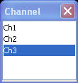
If one or several traces are assigned to the selected channel, one of these traces becomes the active trace.
The order of all channels belonging to a setup is given by the channels' creation time. By default, the channels are named Ch1, Ch2, ... so that Ch<n – 1> precedes Ch<n>. This order is always maintained, even if channels are renamed, invisible (because no traces are assigned to them) or distributed over several diagram areas.
|
Remote control: |
The numeric suffix <Ch> appended to the first-level mnemonic of a command selects a channel as active channel. |
Creates a new channel and a new trace, which is displayed in the active diagram area. The new channel settings (including a possible channel calibration) are identical to the previous channel settings; the trace is created with the trace settings of the former active trace but displayed with another color. The former and the new active trace are superimposed but can be easily separated, e.g. by changing the Reference Position.
The new channel is named Ch<n>, where <n> is the largest of all existing channel numbers plus one. The name can be changed in the Channel Manager.
To create a new trace in the active channel, use
the Trace
– Traces
– Add
Trace
function. To create a new channel and a new
trace and display it in a new diagram area, use Add
Channel + Trace + Diag. Area.
|
Remote control: |
CONFigure:CHANnel<Ch>[:STATe]
ON |
Creates a new channel and a new trace, which is displayed in a new diagram area. The new channel settings (including a possible channel calibration) are identical to the previous channel settings; the trace is created with the trace settings of the former active trace but displayed with another color.
The new channel is named Ch<n>, where <n> is the largest of all existing channel numbers plus one. The name can be changed in the Channel Manager.
To create a new trace in the active channel, use
the Trace
– Traces
– Add
Trace
function. To create a new channel and a new
trace and display it in the active diagram area, use Add
Channel + Trace.
|
Remote control: |
CONFigure:CHANnel<Ch>[:STATe]
ON |
Deletes the active channel including all traces assigned to the channel and removes all display elements related to the channel from the diagram area. Delete Channel is disabled if the setup contains only one channel: In manual control, each setup must contain at least one diagram area with one channel and one trace.
To restore a channel that was unintentionally deleted,
use the Undo
function.
|
Remote control: |
Opens a dialog to perform the actions in the Channel Select menu systematically and rename channels.
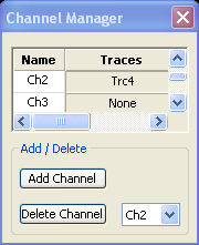
All existing channels of the current setup are listed in a table; see below. Below the table the Trace Manager provides the following buttons:
Add Channel adds a new channel to the list. The new channel is named Ch<n>, where <n> is the largest of all existing channel numbers plus one.
Delete Channel deletes the channel selected in the drop-down menu. This button is disabled if the setup contains only one channel: In manual control, each setup must contain at least one diagram area with one channel and one trace.
Columns
in the Channel Manager table
The channel table contains several editable (white) or non-editable (gray) columns.
Channel indicates the current channel name. The default names for new channels are Ch<n> where <n> is a current number.
Traces indicates the names of all traces assigned to the channel.
|
Remote control: |
CONFigure:CHANnel<Ch>:CATalog? |