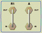
Use these connectors to develop custom measurements. See the block diagram of internal hardware for details.
The upper "A" connector comes from the coupled arm of the Port 1 coupler. The lower connector goes directly to the input of receiver "A." If Option 015 is installed, the path goes directly to a switchable attenuator and then to the receiver.
The upper "R1" connector comes from the transfer switch Reference 1 output. The lower connector goes directly to the R1 receiver input.